
 That venerable electronic test standard IEEE Std 1149.1 (also known as JTAG; also known as Boundary-Scan; also known as Dot 1) has just been freshened up. This is no ordinary freshening. The standard, last revisited in 2001, is long overdue for some clarification and enhancement. It’s been a long time coming and now…it’s here. While the guts remain the same and in good shape, some very interesting options and improvements have been added. The improvements are intended to provide support for testing and verification of the more complex devices currently available and to acknowledge the more sophisticated test algorithms and capabilities afforded by the latest hardware. There is an attempt, as well, (perhaps though, only as well as one can do this sort of thing) to anticipate future capabilities and requirements and to provide a framework within which such capabilities and requirements can be supported. Of course, since the bulk of the changes are optional their value will only be realized if the end-user community embraces them.
There are only some minor clarifications or relaxations to the rules that are already established. For the most part, components currently compliant with the previous version of this standard will remain compliant with this one. There is but one “inside baseball” sort of exception. The long denigrated and deprecated BC_6 boundary-scan cell has finally been put to rest. It is, with the 2013 version, no longer supported or defined, so any component supplier who chose to utilize this boundary-scan cell – despite all warnings to contrary – must now provide their own BSDL package defining this BC_6 cell if they upgrade to using the STD_1149_1_2013 standard package for their BSDL definitions.
While this is indeed a major revision, I must again emphasize that all the new items introduced are optional. One of the largest changes is in documentation capability incorporating the introduction of a new executable description language called Procedural Description Language (PDL) to document test procedures unique to a component. PDL, a TCL-like language, was adopted from the work of the IEEE Std P1687 working group. 1687 is a proposed IEEE Standard for the access to and operation of embedded instruments (1687 is therefore also known as iJTAG or Instrument JTAG). The first iteration of the standard was based on use of the 1149.1 Test Access Port and Controller to provide the chip access—and a set of modified 1149.1-type Test Data Registers to create an access network for embedded instruments. PDL was developed to describe access to and operation of these embedded instruments.
Now, let’s look at the details. The major changes are as follows:
In the standard body:
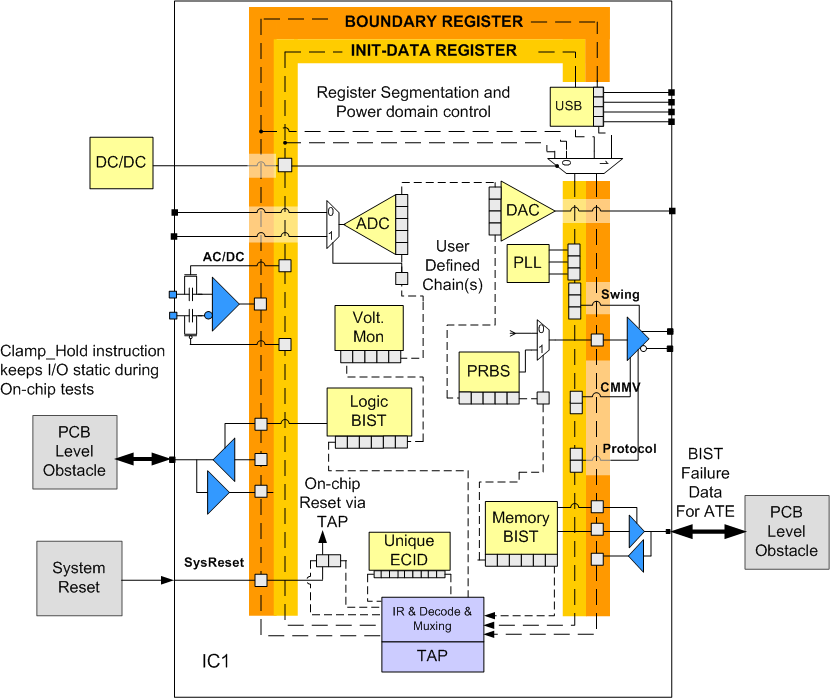
- In order to allow devices to maintain their test logic in test mode, a new, optional, test mode persistence controller was introduced. This means that test logic (like the boundary-scan register) can remain behaviorally in test mode even if the active instruction does not force test mode. To support this, the TAP controller was cleaved into 2 parts. One part that controls test mode and the other that has all the rest of the TAP functionality. In support of this new controller, there are three new instructions: CLAMP_HOLD and TMP_STATUS (both of which access the new TMP status test data register) and CLAMP_RELEASE.
- In recognizing the emerging requirement for unique device identification codes a new, optional ECIDCODE instruction was introduced along with an associated electronic chip identification test data register. This instruction-register pair is intended to supplement the existing IDCODE and USERCODE instructions and allow for access to an Electronic Chip Identification value that could be used to identify and track individual integrated circuits.
- The problem of initializing a device for test has been addressed by providing a well-defined framework to use to formalize this process. The new, optional INIT_SETUP, INIT_SETUP_CLAMP, and INIT_RUN instructions paired with their associated initialization data and initialization status test data registers were provided to this end. The intent is that these instructions formalize the manner in which programmable input/output (I/O) can be set up prior to board or system testing, as well as any providing for the execution of any tasks required to put the system logic into a safe state for test.
- Recognizing that resetting a device can be complex and require many steps or phases, a new, optional, IC_RESET instruction and its associated reset_select test data register is defined to provide formalized control of component reset functions through the TAP.
- Many devices now have a number of separate power domains that could result in sections of the device being powered down while other are powered up. A single, uniform boundary-scan register does not align well with that device style. So to support power domains that may be powered down but having a single test data register routed through these domains, an optional standard TAP to test data register interface is recommended that allows for segmentation of test data registers. The concept of register segments allows for segments that may be excluded or included and is generalized sufficiently for utilization beyond the power domain example.
- There have also been a few enhancements to the boundary-scan register description to incorporate the following:
1. Optional excludable (but not selectable) boundary-scan register segments
2. Optional observe-only boundary-scan register cells to redundantly capture the signal value on all digital pins except the TAP pins
3. Optional observe-only boundary-scan register cells to capture a fault condition on all pins, including non-digital pins, except the TAP pins.
The Boundary Scan Description Language annex was rewritten and includes:
- Increased clarity and consistency based on end-user feedback accumulated over the years.
- A technical change was made such that BSDL is no longer a “proper subset” of VHDL, but it is now merely “based on” VHDL. This means that BSDL now maintains VHDL’s flavor but has for all intents and purposes been “forked”.
- As result of this forking, formal definitions of language elements are now included in the annex instead of reliance on inheritance from VHDL.
- Also as a result of this forking, some changes to the BNF notation used, including definition of all the special character tokens, are in the annex.
- Pin mapping now allows for documenting that a port is not connected to any device package pin in a specific mapped device package.
- The boundary-scan register description introduces new attributes for defining boundary-scan register segments, and introduces a requirement for documenting the behavior of an un-driven input.
- New capabilities are introduced for documenting the structural details of test data registers:
1. Mnemonics may be defined that may be associated with register fields.
2. Name fields within a register or segment may be defined.
3. Types of cells used in a test data register (TDR) field may be defined.
4. One may hierarchically assemble segments into larger segments or whole registers.
5. Constraints may be defined on the values to be loaded in a register or register field.
6. A register field or bit may be associated with specific ports
7. Power port may be associated with other ports. - The User Defined Package has been expanded to support logic IP providers who may need to document test data register segments contained within their IP.
As I stated earlier, a newly adopted language, PDL, has been included in this version of the standard. The details of this language are included as part of Annex C. PDL is designed to document the procedural and data requirements for some of the new instructions. PDL serves a descriptive purpose in that regard but, as such, it is also executable should a system choose to interpret it.
It was decided to adopt and develop PDL to support the new capability of initializing internal test data register fields and configuring complex I/Os prior to entering the EXTEST instruction. Since the data required for initialization could vary for each use of the component on each distinct board or system design there needed to be an algorithmic way to describe the data set-up and application., in order to configure the I/O Since this version of the standard introduces new instructions for configuring complex I/Os prior to entering the EXTEST instruction. As the data required for initialization could vary for each use of the component on each distinct board or system design, this created the need for a new language for setting internal test data register fields in order to configure the I/O. It was decided to adopt PDL and tailor it to the BSDL register descriptions and the needs of IEEE 1149.1.
Since the concept of BSDL and PDL working together is new and best explained via examples Annex D is provided to supply extended examples of BSDL and PDL used together to describe the structure and the procedures for use of new capabilities. Similarly Annex E provides example pseudo-code for the execution of the PDL iApply command, the most complex of the new commands in PDL.
So that is the new 1149.1 in a nutshell. A fair amount of new capabilities. Some of it complex. All of it optional. Will you use it?